Call-Hierarchy and Data Flow Graph
For presenting relation between projects functions and data, a graphical presentation called the Call-Hierarchy Graph is used in many variations. Using grouping possibilities apart from individual functions and data the graph can display parts of the project at various levels: module group, function group or data group as well as function parameters. Links between nodes display function calls, transfer of parameters and results among functions, changing or using data in functions.
Overview
Basic Call-Hierarchy Graph Elements
Operations Independent of Graph Type
Operations Specific to the Call-Hierarchy Graph
Groups and Views in Call-Hierarchy Graph
Overview
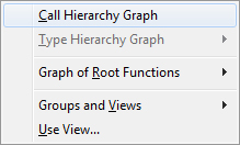
When the Editor is open in DA-C and the insertion point is positioned within a function name, the Graph menu appears as on the following figure:
Menu for starting a graph
By starting the Graph / Call-Hierarchy graph command, you open the corresponding Call-Hierarchy Graph. Another way to open a Call-Hierarchy Graph is to start the shortcut menu command which is enabled by right-clicking the corresponding symbol in Editor as on the following figure.
The following group of functions is represented by the Call-Hierarchy graph in the picture below:
Shortcut menu for starting a Call-Hierarchy Graph
You can open a similar menu by right-clicking a symbol in the Browser or the Logical view tab of Project Explorer.
You can also open Call-Hierarchy Graphs on the basis of defined views.
A specific case of the Call-Hierarchy Graph is obtained by starting the Graph / Graph of Root Functions command. In such a graph, the nodes of project functions which were not called by other project functions are displayed.

Basic Call-Hierarchy Graph Elements
Basic graph elements are: function, parameter and function result, global or module global data (variable and constant). The Call-Hierarchy Graph does not display local data.
Function Nodes
Functions are represented by rectangular nodes. The name of the function appears in the node as does the name of the module in which the function is defined/implemented.
The shape of the inner frame contains information on the function visibility range: public or static and library (not defined in the project source code). Node background color is adjustable.
Types of function nodes in the Call-Hierarchy Graph
Call and Data Flow Branches
The node of the calling and the node of the called function are connected by a graph branch pointing from the calling to the called function.
A function can call another function several times and each call is represented by a separate branch in the graph. The grouping of these branches into a single branch with or without listing the number of call is adjustable.
The shape of the branch which connects the node of the calling function with the node of the called function depends on the type and number of parameters and results. A thin arrow always indicates the direction of the calling. A fuller arrow indicates the direction of data transfer.
The direction of data transfer can be from the calling function to the function called if there are parameters which are transferred according to value and reference. If there is transfer of parameter according to reference or the function called returns the result, the direction of transfer will be from the node of the function called to the node of the calling function.
Parameter Nodes
If data flow is displayed, the branch from the node of the calling function to the node of the function called is "cut" and the node of parameters and results (the parameter node) is inserted. The node is rectangular with a bold upper and lower edge. The parameter number (or nothing, if the function called does not have a parameter) and the result type appear in the node.
In Graph Options you can specify whether parameter nodes will be displayed or not.
Data Nodes
Data (variables and constants) can be global, global at module level (module global) or local. Call-Hierarchy Graphs display global and module global data because they represent one of the ways of exchanging data between functions.
Data nodes are rectangular with a bold upper and lower edge. The name of the piece of data, "const" if a constant is in question and the name of the file where it is defined appear in the node.
As with function nodes, data nodes with shapes and colors indicate whether the piece of data is global (public) or module global (static) and whether it is defined outside the source code program (library).
Types of data nodes
Branches between Function Nodes and Data Nodes
Graph branches display the direction of data flow. Each individual change or use of data is represented by a separate graph branch. The arrows on these branches are full. Branch color can be adjusted separately for both directions of data flow.
The following situations come under the heading of using data within a function:
- The data appears to the right of the assignment operator (=)
- The data appears in self-incrementing, self-decrementing, self-shifting expressions and so on
- The data appears in logical block conditions
- The data is transferred either according to value or reference as the parameter of another function.
The following situations fall under the heading of changing data within a function:
- The data appears to the left of the assignment operator (=)
- The data appears in self-incrementing, self-decrementing, self-shifting expressions, and so on
- The data is transferred according to reference as the parameter of another function.
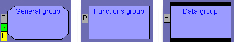
Group Nodes
Group nodes represent sets of functions or project data and in this way enable the display of global relations between module and group of modules or interface and module. Group nodes can contain, apart from functions and data, other groups by means of which an arbitrary hierarchy can be formed.
In the Call-Hierarchy Graph there are three types of groups which are defined by their content: groups containing only functions (function groups), groups containing only data (data groups), and groups containing both functions and data (general groups). The validity area of the group members is also displayed in group nodes (P = public, S = Static and L = Library).
The external shape of group nodes is the same and is given in following figure, while the shape of the inner frame depends on the type of group members. In the same figure, you can see the difference between types of group nodes.
Types of group nodes
Group nodes contain functions and data which can be linked (function call, data use) with other functions and data which are not in the group. The branches between a group node and other nodes in the graph (which can also be group nodes) represent the connection between basic elements of the group and elements outside the group.
The operation of grouping graph nodes is described in Chapter Groups and Views in Call-Hierarchy Graph.